Product Description
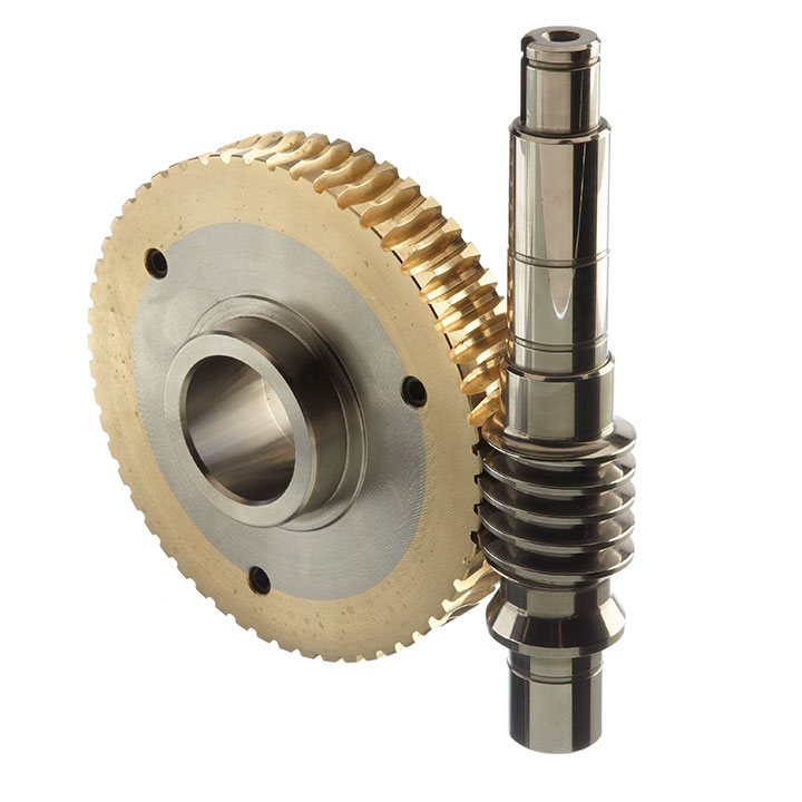
Flange Mounted Planar Double Enveloping Worm Gear Unit
Working conditions
Two shafts for 90 ° Intersect, input speed must not be more than 1500 rpm.The working environment temperature should range from 0 ~ 40 ° C, when the environment temperature below 0 ° C or above 40 ° C.Before starting the lubricating oil to corresponding heating and cooling, The worm shafts, reverse operation can be positive.
Data sheet on CUW double enveloping worm gear reducer :
| Model | ShaftDia. (mm) | Center Height (CUW) | (CUW) Output shaft Dia. | Power | Ratio | Permitted Torque | Weight |
| (CUW) input Solid(h6) | (mm) | (mm) | (kw) | (Nm) | (KGS) | ||
| 100 | 28 | 190 | 48 | 1.41~11.5 | 10 .25~ 62 | 683-1094 | 42 |
| 125 | 32 | 225 | 55 | 2.42~19.7 | 10 .25 ~ 62 | 1170~2221 | 65 |
| 140 | 38 | 255 | 65 | 3.94~25.9 | 10 .25 ~ 62 | 1555 ~ 3473 | 85 |
| 160 | 42 | 290 | 70 | 4.39~35.7 | 10 .25 ~ 62 | 2143 ~4212 | 120 |
| 180 | 48 | 320 | 80 | 5.83~47.5 | 10 .25 ~ 62 | 2812 ~ 5387 | 170 |
| 200 | 55 | 350 | 90 | 7.52 ~61.2 | 10 .25 ~ 62 | 3624 ~6859 | 220 |
| 225 | 60 | 390 | 100 | 9.9~81.4 | 10 .25 ~ 62 | 4872 ~ 9224 | 290 |
| 250 | 65 | 430 | 110 | 12.9 ~105 | 10 .25~ 62 | 6284~11892 | 380 |
| 280 | 70 | 480 | 120 | 16.9 ~ 138 | 10 .25 ~ 62 | 8347 ~ 15820 | 520 |
| 315 | 75 | 530 | 140 | 22.5 ~183 | 10 .25 ~ 62 | 11068~ 19450 | 700 |
| 355 | 80 | 595 | 150 | 30~245 | 10 .25 ~ 62 | 14818 ~28014 | 1030 |
| 400 | 90 | 660 | 170 | 32.1 ~261 | 10 .25 ~ 62 | 15786~29918 | 1400 |
| 450 | 100 | 740 | 190 | 42.6 ~347 | 10 .25 ~ 62 | 2571~39881 | 1980 |
| 500 | 110 | 815 | 210 | 54.9 ~ 448 | 10 .25 ~ 62 | 27097~51180 | 2700 |
/* January 22, 2571 19:08:37 */!function(){function s(e,r){var a,o={};try{e&&e.split(“,”).forEach(function(e,t){e&&(a=e.match(/(.*?):(.*)$/))&&1
| Application: | Motor, Machinery, Marine, Agricultural Machinery |
|---|---|
| Function: | Distribution Power, Change Drive Torque, Change Drive Direction, Speed Changing, Speed Reduction, Speed Increase |
| Layout: | Angle |
| Hardness: | Hardened Tooth Surface |
| Installation: | Horizontal Type |
| Step: | Single-Step |
| Samples: |
US$ 500/Piece
1 Piece(Min.Order) | |
|---|
| Customization: |
Available
| Customized Request |
|---|

What lubrication is required for a worm gear?
The lubrication requirements for a worm gear system are crucial to ensure smooth operation, reduce friction, prevent wear, and extend the lifespan of the gears. The specific lubrication needed may vary depending on factors such as the application, operating conditions, gear materials, and manufacturer recommendations. Here are some key considerations regarding lubrication for a worm gear:
- Lubricant selection: Choose a lubricant specifically designed for gear applications, taking into account factors such as load, speed, temperature, and environment. Common lubricant types for worm gears include mineral oils, synthetic oils, and greases. Consult the gear manufacturer’s recommendations or industry standards to determine the appropriate lubricant type and viscosity grade.
- Viscosity: The lubricant viscosity is critical for effective lubrication. The viscosity should be selected based on the operating conditions and gear design parameters. Higher loads and slower speeds typically require higher viscosity lubricants to ensure sufficient film thickness and protection. Conversely, lower viscosity lubricants may be suitable for lighter loads and higher speeds to minimize power losses.
- Lubrication method: The lubrication method can vary depending on the gear system design. Some worm gears have oil sumps or reservoirs that allow for oil bath lubrication, where the gears are partially submerged in a lubricant pool. Other systems may require periodic oil application or greasing. Follow the gear manufacturer’s guidelines for the appropriate lubrication method, frequency, and quantity.
- Temperature considerations: Worm gear systems may encounter a wide range of temperatures during operation. Ensure that the selected lubricant can withstand the anticipated temperature extremes without significant degradation or viscosity changes. Extreme temperatures may require specialized high-temperature or low-temperature lubricants to maintain proper lubrication performance.
- Maintenance and monitoring: Regular maintenance and monitoring of the lubrication are essential for optimal gear performance. Periodically inspect the lubricant condition, including its cleanliness, viscosity, and contamination levels. Monitor operating temperatures and perform oil analysis if necessary. Replace the lubricant at recommended intervals or if signs of degradation or contamination are observed.
It’s important to note that the lubrication requirements may vary for different worm gear applications, such as automotive, industrial machinery, or marine systems. Additionally, environmental factors such as dust, moisture, or chemical exposure should be considered when selecting a lubricant and establishing a lubrication maintenance plan.
Always refer to the gear manufacturer’s recommendations and guidelines for the specific lubrication requirements of your worm gear system. Adhering to proper lubrication practices helps ensure smooth and reliable operation, minimizes wear, and maximizes the gear system’s longevity.

How do you address noise and vibration issues in a worm gear system?
Noise and vibration issues can arise in a worm gear system due to various factors such as misalignment, improper lubrication, gear wear, or resonance. Addressing these issues is important to ensure smooth and quiet operation of the system. Here’s a detailed explanation of how to address noise and vibration issues in a worm gear system:
1. Misalignment correction: Misalignment between the worm and the worm wheel can cause noise and vibration. Ensuring proper alignment of the gears by adjusting their positions and alignment tolerances can help reduce these issues. Precise alignment minimizes tooth contact errors and improves the meshing efficiency, resulting in reduced noise and vibration levels.
2. Lubrication optimization: Inadequate or improper lubrication can lead to increased friction and wear, resulting in noise and vibration. Using the correct lubricant with the appropriate viscosity and additives, and ensuring proper lubrication intervals, can help reduce friction and dampen vibrations. Regular lubricant analysis and replenishment can also prevent excessive wear and maintain optimal performance.
3. Gear inspection and replacement: Wear and damage to the gear teeth can contribute to noise and vibration problems. Regular inspection of the worm gear system allows for early detection of any worn or damaged teeth. Timely replacement of worn gears or damaged components helps maintain the integrity of the gear mesh and reduces noise and vibration levels.
4. Noise reduction measures: Various noise reduction measures can be implemented to minimize noise in a worm gear system. These include using noise-dampening materials or coatings, adding sound insulation or vibration-absorbing pads to the housing, and incorporating noise-reducing features in the gear design, such as profile modifications or helical teeth. These measures help attenuate noise and vibration transmission and improve overall system performance.
5. Resonance mitigation: Resonance, which occurs when the natural frequency of the system matches the excitation frequency, can amplify noise and vibration. To mitigate resonance, design modifications such as changing gear stiffness, altering the system’s natural frequencies, or adding damping elements can be considered. Analytical tools like finite element analysis (FEA) can help identify resonant frequencies and guide the design changes to reduce vibration and noise.
6. Isolation and damping: Isolation and damping techniques can be employed to minimize noise and vibration transmission to the surrounding structures. This can involve using resilient mounts or isolators to separate the gear system from the rest of the equipment or incorporating damping materials or devices within the gear housing to absorb vibrations and reduce noise propagation.
7. Tightening and securing: Loose or improperly tightened components can generate noise and vibration. Ensuring that all fasteners, bearings, and other components are properly tightened and secured eliminates sources of vibration and reduces noise. Regular inspections and maintenance should include checking for loose or worn-out parts and addressing them promptly.
Addressing noise and vibration issues in a worm gear system often requires a systematic approach that considers multiple factors. The specific measures employed may vary depending on the nature of the problem, the operating conditions, and the desired performance objectives. Collaborating with experts in gear design, vibration analysis, or noise control can be beneficial in identifying and implementing effective solutions.

Understanding Worm Gears and Their Operation
A worm gear is a type of mechanical gear that consists of a threaded screw-like component (called the worm) and a toothed wheel (called the worm gear). It is used to transmit motion between non-intersecting and perpendicular shafts. Here’s how it works:
The worm, typically in the form of a cylindrical rod with a helical thread, meshes with the teeth of the worm gear. When the worm is rotated, its threads engage with the teeth of the worm gear, causing the gear to rotate. The direction of rotation of the worm gear is perpendicular to the axis of the worm.
One significant feature of worm gears is their ability to provide high gear reduction ratios. The number of teeth on the worm gear relative to the number of threads on the worm determines the reduction ratio. This makes worm gears suitable for applications where high torque and low-speed rotation are required.
Worm gears are commonly used in various mechanical systems, such as conveyor systems, lifts, automotive steering mechanisms, and more. Their unique design also provides a self-locking feature: when the system is not actively rotating the worm, the gear cannot easily backdrive the worm due to the angle of the threads, providing mechanical advantage and preventing reverse motion.


editor by Dream 2024-04-25
by
Tags:
Leave a Reply